Usage
Aloha can monitor up to 16 voltage sources at the same time. These voltages may be produced by power supplies, sensors, voltage references... In the following, a sensor is used as an example, but the procedure and results are exactly the same for other voltage sources.
Electrical specifications
The key parameter that must be observed is the input voltage range. Each analog input (or channel) is suited for continuous as well as alternative voltages ranging from -50V to 50V.
It is important to note that Aloha cannot monitor fast-changing voltage sources du to sampling frequency limits. Hence, if you choose to monitor an voltage source, make sure its maximum frequency is below 100Hz. Otherwise, results will not be accurate or meaningful.
All channels are independant and their respective analog-to-digital converters are isolated from other subsystems within Aloha.
The input impedance on each channel is about one megaohm.
Electrical wiring
Pinout
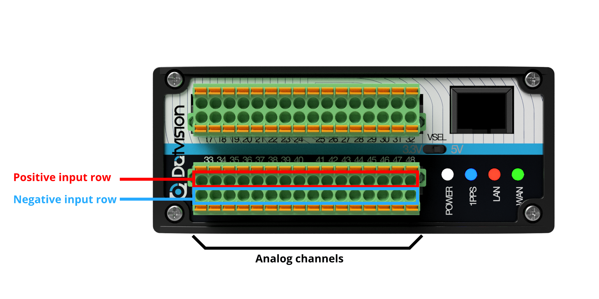
Each analog channel is comprised of an input pair: a positive input and a negative input. These input pairs are located on the lower front connector. The top row of this connector holds all positive inputs while the bottom row holds the negative inputs. Hence, positive inputs range from pin n°33 to pin n°48 and negative inputs range from pin n°49 to pin n°64. Then, available pin pairs are 33-49, 34-50, ..., 48-64:

The analog channels are controlled by two analog-to-digital converters. Each is responsible for 8 analog channels, ranging from channel 0 to channel 7:
| ADC1 | |||||||
| Pins 33 & 49 | Pins 34 & 50 | Pins 35 & 51 | Pins 36 & 52 | Pins 37 & 53 | Pins 38 & 54 | Pins 39 & 55 | Pins 40 & 56 |
| Channel 0 | Channel 1 | Channel 2 | Channel 3 | Channel 4 | Channel 5 | Channel 6 | Channel 7 |
| ADC2 | |||||||
| Pins 41 & 57 | Pins 42 & 58 | Pins 43 & 59 | Pins 44 & 60 | Pins 45 & 61 | Pins 46 & 62 | Pins 47 & 63 | Pins 48 & 64 |
| Channel 0 | Channel 1 | Channel 2 | Channel 3 | Channel 4 | Channel 5 | Channel 6 | Channel 7 |
Connection architecture
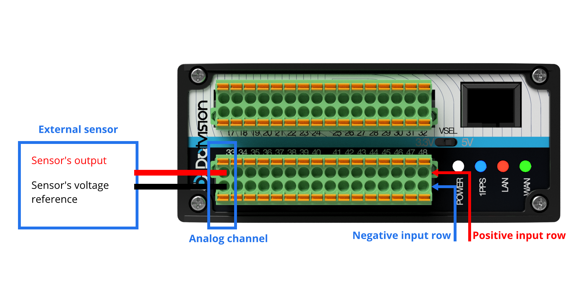
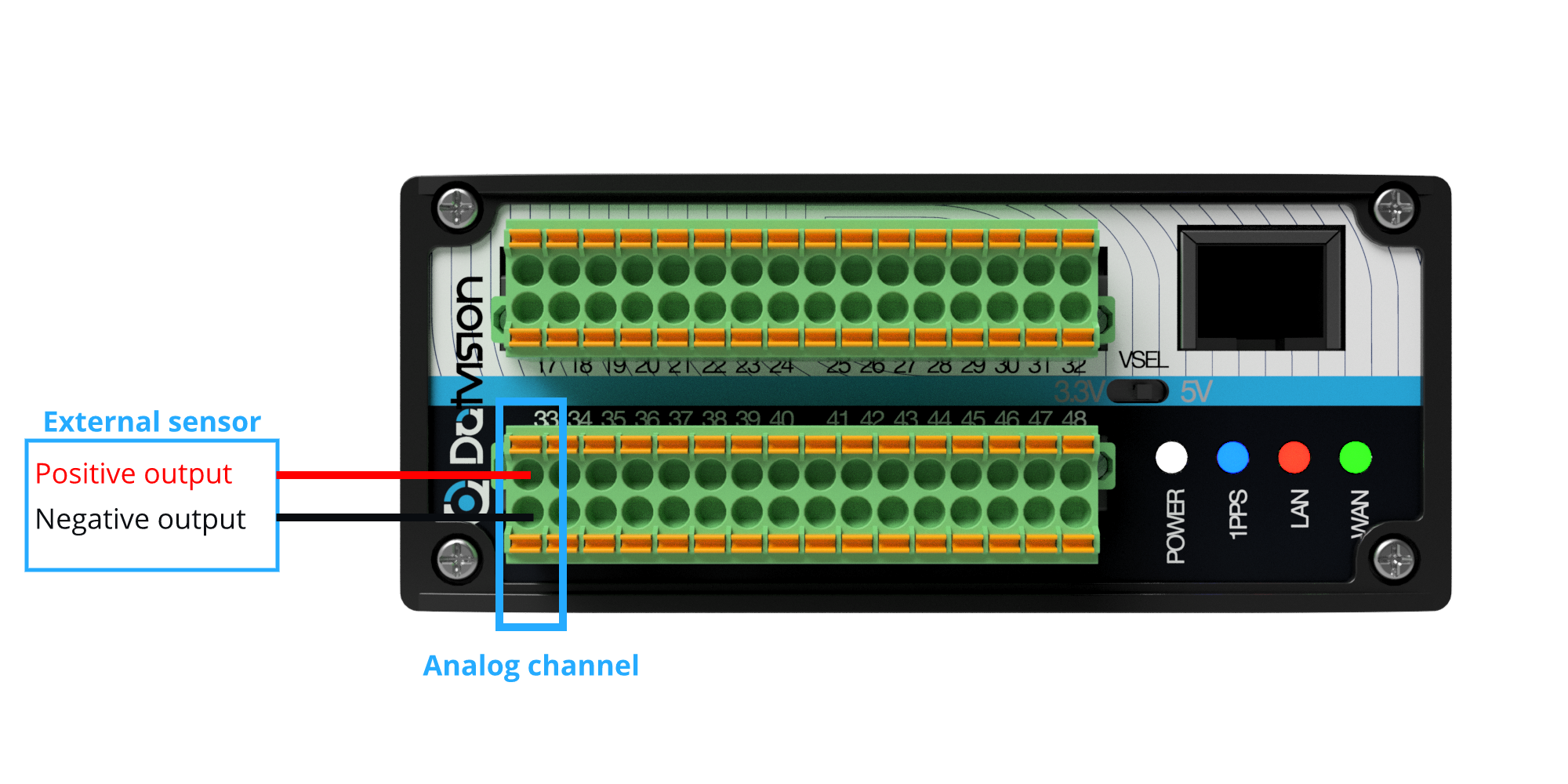
Analog inputs can be connected to sensors in two different ways: single-ended or differential. Below are shown two examples using the ADC1 and its analog channel 0.
In a single-ended configuration, the sensor's voltage reference is connected to the negative input of the analog channel while the sensor's output is connected to the positive input of the channel:

In a differential configuration, the sensor's reference voltage is not used and is replaced by its negative output:

In either configuration, should the polarity be reversed the result will be opposite to the measured voltage.


Comments
0 comments
Please sign in to leave a comment.