4.2 Front panel, microSD card and reset button access.
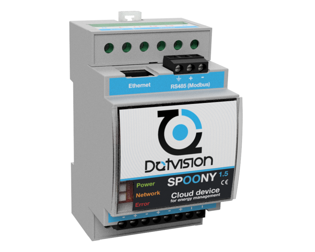
Visual characteristics of actual product may differ. Colors and terminals type may differ for older or newer revision of the product.
1 Presentation
Spoony by DotVision can be described as an Energy Edge Gateway, a single device holding key functionalities for energy monitoring:
- Single and three-phase energy measurement,
- Network connectivity allowing direct connection to a storage server (cloud-based or on-premises),
- Local data storage,
- Data aggregation thanks to integrated MODBUS client functionality (Option - RS485 and TCP) and TIC demodulator functionality,
- Control-command with 3 integrated open-drain outputs suitable to drive up to three relays.
Spoony integrated software is based on BluePanda operating system by DotVision, providing unprecedented flexibility in terms of configuration and product customization. Contact DotVision for any question related to product customization or new protocols integration.
2 Technical specifications
|
Product name |
Spoony |
|
Manufacturer |
DotVision |
|
Size |
90 x 60 x 53mm |
|
Format |
DIN-rail mount module, 53mm width (3 ½ modules). Compatible with Omega type rails |
|
Environmental |
IP20 |
|
Casing material |
ABS |
|
Power supply input range |
80-270 VAC, 50-60Hz. 0.2A max |
|
Temperature range |
-10°C to 60°C |
|
Humidity |
Max 80% non-condensing |
|
Certifications |
Standard conformity to European Directives (CE) for low voltage and CEM, ROHS, REACH |
|
Voltage measurement inputs range |
400Vpp Line to Neutral, 800Vpp Line to Line Input impedance: ≥ 2MΩ |
|
Current measurement mode |
Indirect, through current transformers or Rogowski coils |
|
Current measurement inputs |
Current transformers version: ±100mA, Impedance: 5Ω Rogowski coils version: ±250mV, Impedance ≥ 380kΩ |
|
Current measurement range |
Depending on current transformers or Rogowski coils choice. Refer to sensor datasheet. |
|
Electrical Network type |
Single-phase or three-phase electrical networks, with or without neutral 1. |
|
Measurement Bandwidth (-3dB) |
IRMS, power: 14kHz VRMS: 260Hz |
|
Measurements update frequency |
1Hz for all measurements |
|
Metering IC |
Analog Devices ADE7758 |
|
Connection |
Power and voltage measurement: screw terminals, 0.2 to 1.5mm² Current measurement: push terminals, 0.1 to 0.75mm² RS485, TIC, relays: screw terminals Network: RJ45 |
|
Accuracy |
RMS voltage measurement: 1% over 20:1 dynamic range RMS current measurement: depending on current sensor choice. Typical 1% over 20:1 dynamic range for sensors provided by DotVision 2. Active power/energy measurement: depending on current sensor choice. Typical 1% over 20:1 dynamic range for sensors provided by DotVision 2. |
Figure 1 – Technical specifications
Note 1: A neutral connection may still be required for powering the device due to the limited input range of power input.
Note 2: Devices provided by DotVision are always calibrated together with provided current sensors for optimal accuracy. Accuracy is not guaranteed if current sensors are replaced without proper calibration. Consult DotVision if you need to change the current sensors provided with the device to determine if a calibration is required.
3 Terminals’ description
Terminals’ pinout is indicated onto the product. Pinout is available here for convenience:
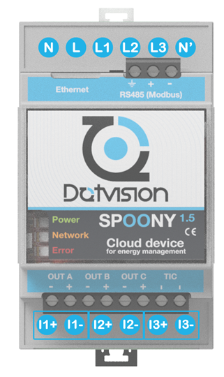
Figure 2- Main terminals’ pinout
N, L: Power supply inputs. 80 to 270 VAC, 50-60Hz
L1, L2, L3, N’: Voltage measurement inputs. Refer to next chapter for details
Ix+ / Ix-: Current measurement inputs (x = 1, 2 or 3)
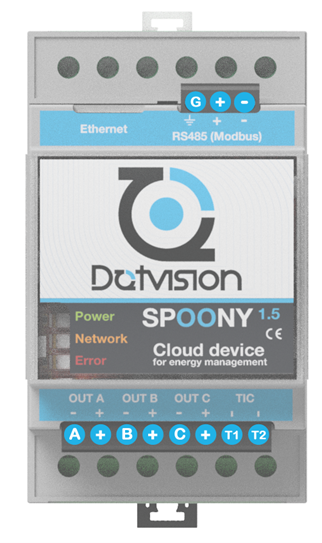
Figure 3- Auxiliary terminals’ pinout
A, B, C: Open-drain relay outputs
+: +12V outputs
T1, T2: TIC demodulator input
4 Device front panel
4.1 Light indicators
Device front panel includes three LED indicators which give information on the device status.
These LEDs are labelled as follow:
Power - Green
Network - Orange
Error – Red
The following list summarizes possible states for the LEDs:
Blinking: the LED is ON for 500ms and OFF for 500ms,
Flashing: the LED is OFF for 2000ms and briefly ON for 80ms,
On: the LED is continuously ON,
Off: the LED is continuously OFF,
X: the LED state is undefined.
The related device status is given in the table below:
|
POWER |
NETWORK |
ERROR |
Device Status |
|
Blinking |
X |
X |
The device is initializing. If network connection is not configured on the device (Data logger mode), the device will stay in this mode |
|
Flash |
X |
X |
The device is running and has established a network connectivity since its startup |
|
X |
Off |
X |
Network connection is down |
|
X |
On |
X |
Network connection is up. If DHCP is activated, the device obtained a valid IP lease |
|
X |
X |
Blinking |
MicroSD card is not properly inserted, or device configuration is invalid |
Figure 4- LEDs indicators signification
4.2 Front panel, microSD card and reset button access
Device’s front panel can be lifted from the bottom side to access microSD card and the reset button, as shown in the figure below:
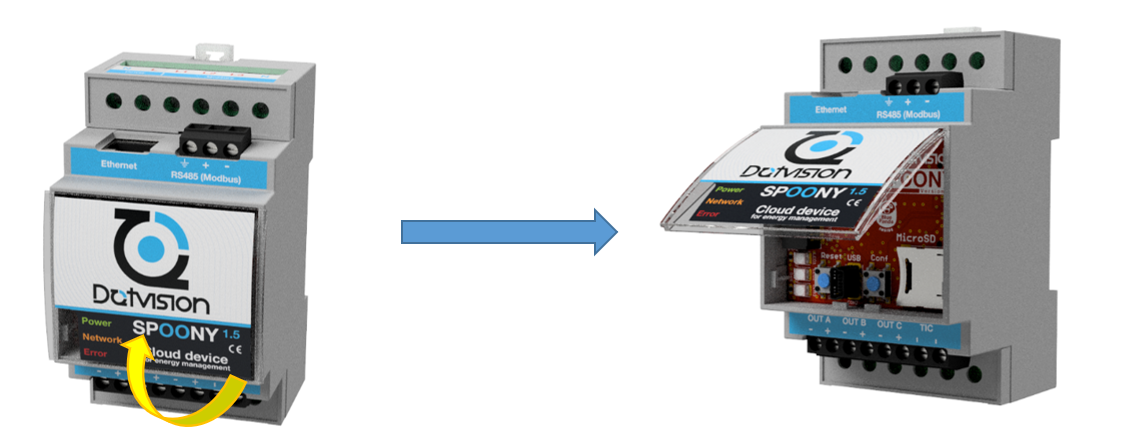
The following figure shows front panel’s key elements:
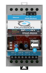
1 – Micro SD card holder. MicroSD card is extracted by sliding the connector cap in the direction indicated by the arrow.
2 – Reset button. Press this button to restart the device. Reset is required after a firmware update for example (see chapter 4.12).
Figure 1 – Technical specifications
Figure 2- Main terminals’ pinout
Figure 3- Auxiliary terminals’ pinout


Comments
0 comments
Please sign in to leave a comment.